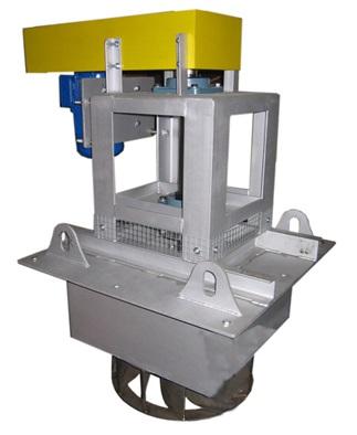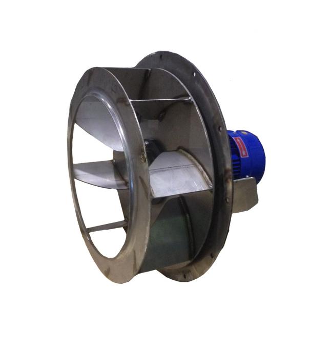
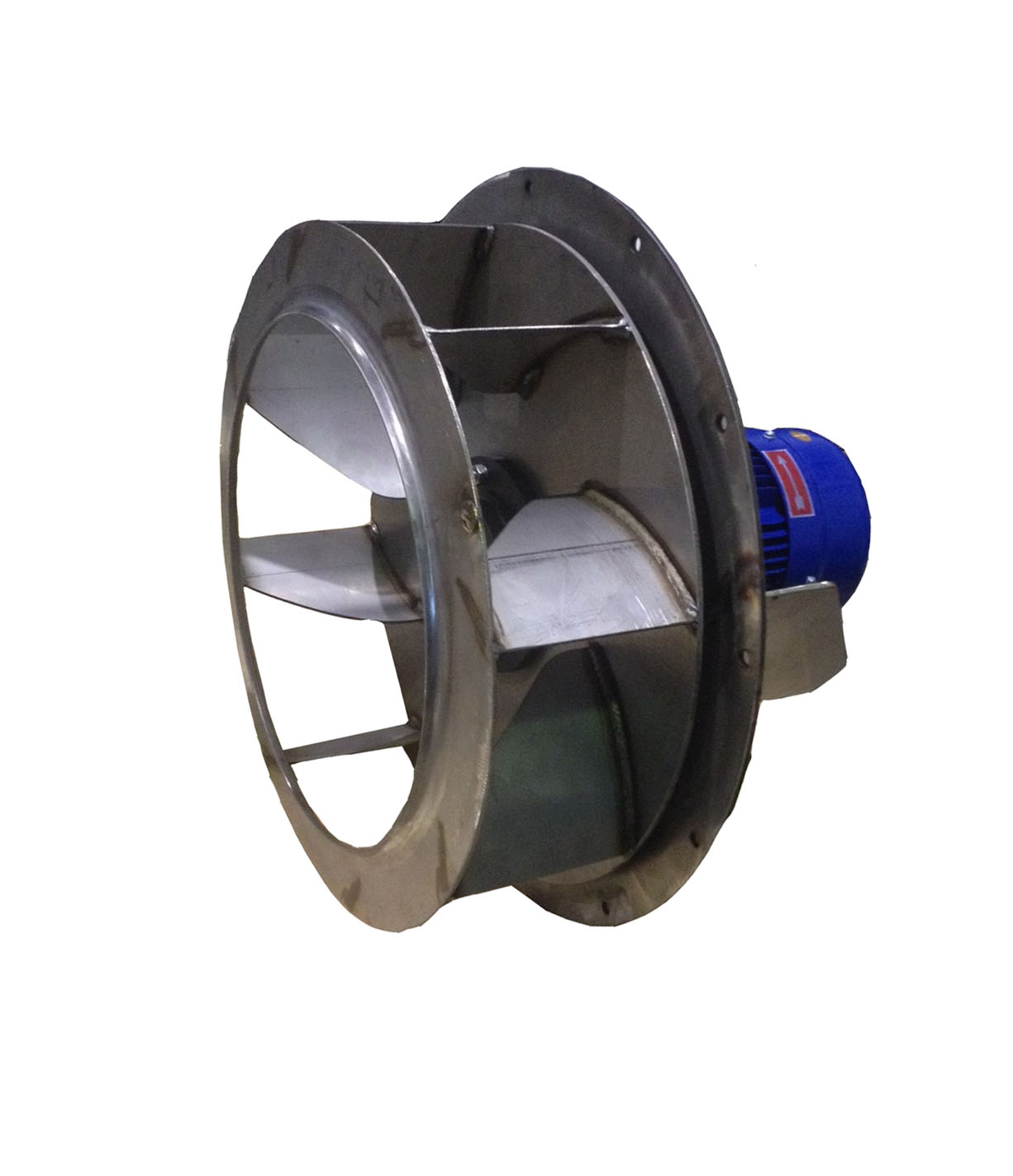
These fans are primarily used for air recirculation within furnaces, where their role is to promote uniform heat distribution and prevent thermal stratification. This helps stabilize the process and maintain more homogeneous conditions in the working chamber. The construction configuration varies based on operating temperatures: they can be made with a directly coupled impeller to the motor for applications up to 90 °C, or with a motor and extended shaft for use up to 300 °C. For higher temperatures, a transmission version is available, suitable for up to 800 °C. The materials are chosen based on the operating environment and can include electro-welded and painted sheet metal with varying thicknesses, stainless steel, or other specific steels for high temperatures.
The Centrifugal Fan Execution Graph is suitable for industrial processes where it is necessary to handle airborne emissions. The configuration can be adapted to a single workstation or integrated into an existing extraction system, helping to keep the working air more stable and controlled.
The Centrifugal Fan Execution Graph is designed to handle airborne emissions through a modular filtration system, using selected filter elements to ensure operational continuity. The possible presence of multiple filtration stages is defined based on the particle size and concentration of the contaminants.
For the Centrifugal Fan Execution Graph, sizing depends on capture distance, intake geometry, and system pressure losses. When available, the indicative range corresponds to the airflow required at the capture point; in any case, it is recommended to verify the data based on the actual emission point and operating conditions.
The Centrifugal Fan Execution Graph requires periodic checks of filters, gaskets, and seals, as well as cleaning or replacement of the filter elements according to the workload. In versions equipped with self-cleaning systems, it is useful to monitor differential pressure and plan maintenance before performance decreases.
To properly integrate the Centrifugal Fan Execution Graph, attention must be paid to positioning relative to the source, sealing of connections, and accessibility for inspection and maintenance. It is also important to verify compatibility with company safety procedures and with the characteristics of the treated contaminants.